Some time ago, a precision gear reducer manufacturer presented the DILAMA technical team with a problem encountered in actual production:
“All precision inspection results for the worm gear meet the requirements, so why does noise and vibration still occur after it is installed in the gearbox?”
In the customer’s existing inspection process, the worm had already undergone testing for key parameters such as tooth profile and lead; however, during actual assembly and operation, the product’s transmission performance still failed to meet expectations. After technical discussions and analysis, it was discovered that the problem did not stem from any single dimensional parameter, but rather was related to the worm’s complex spatial helical tooth surface characteristics, comprehensive tooth surface errors, and the consistency of inspection data.
Traditional inspection methods typically use different equipment to measure parameters such as tooth profile, helix line, and lead separately. Multiple clamping operations and repeated positioning can easily cause reference shifts, making it difficult to conduct a comprehensive analysis of all inspection data within a unified coordinate system.
Consequently, it is common on the production floor for inspection results to meet requirements, yet noise and vibration issues to persist after assembly. At the same time, the lack of comprehensive tooth surface data makes it difficult to quickly pinpoint the causes of anomalies, thereby affecting product quality control and process optimization.
ECON 30 Worm Gear Measurement Solution
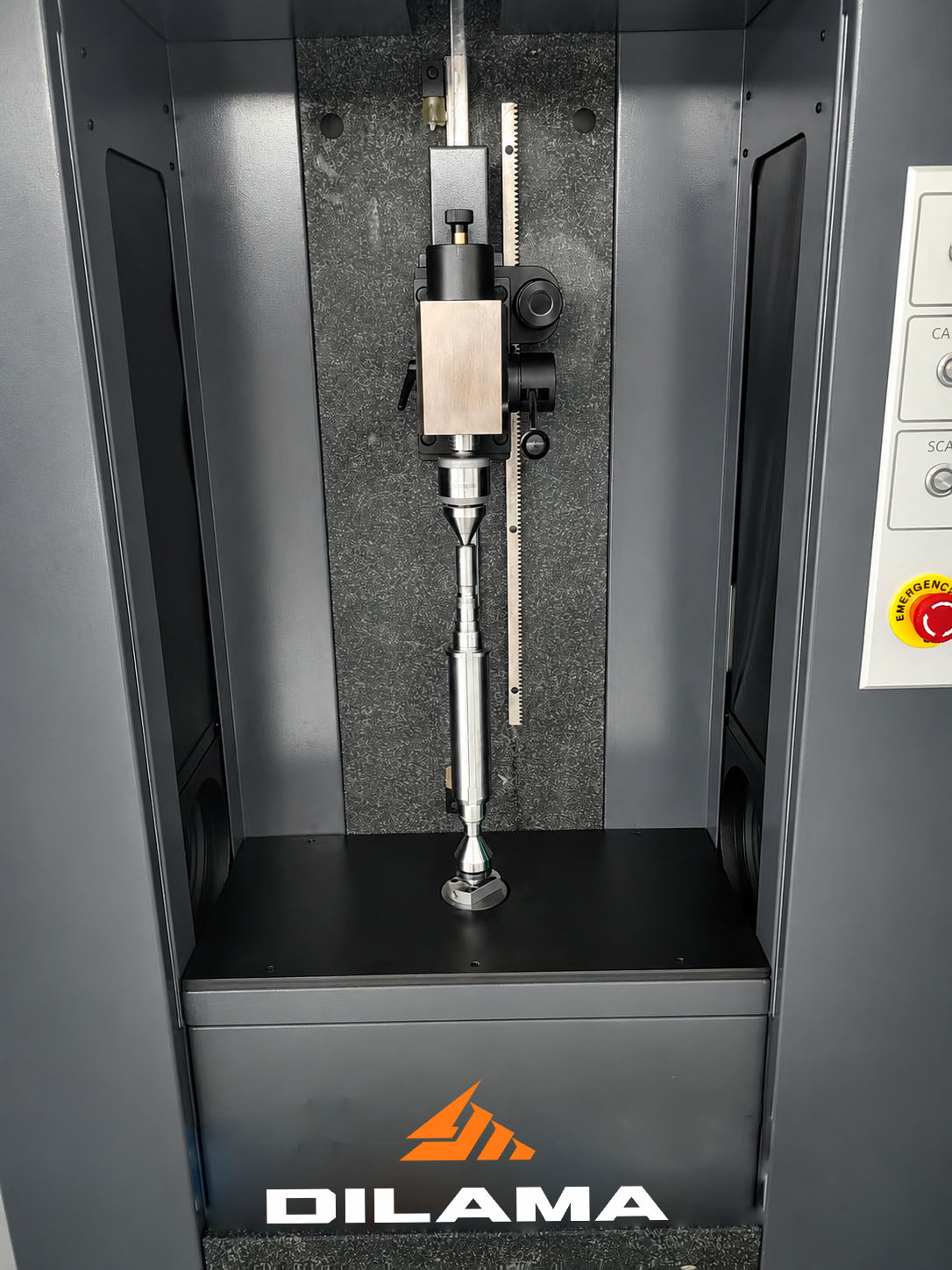
To address the issue of worm gears that “pass dimensional inspections but exhibit unstable actual transmission performance,” DILAMA has introduced the ECON 30 Gear Measurement Center Precision Inspection Solution for Worm Gears. By upgrading from single-parameter inspection to comprehensive spatial tooth surface analysis, this solution enables a thorough evaluation of the key factors affecting worm gear meshing performance.
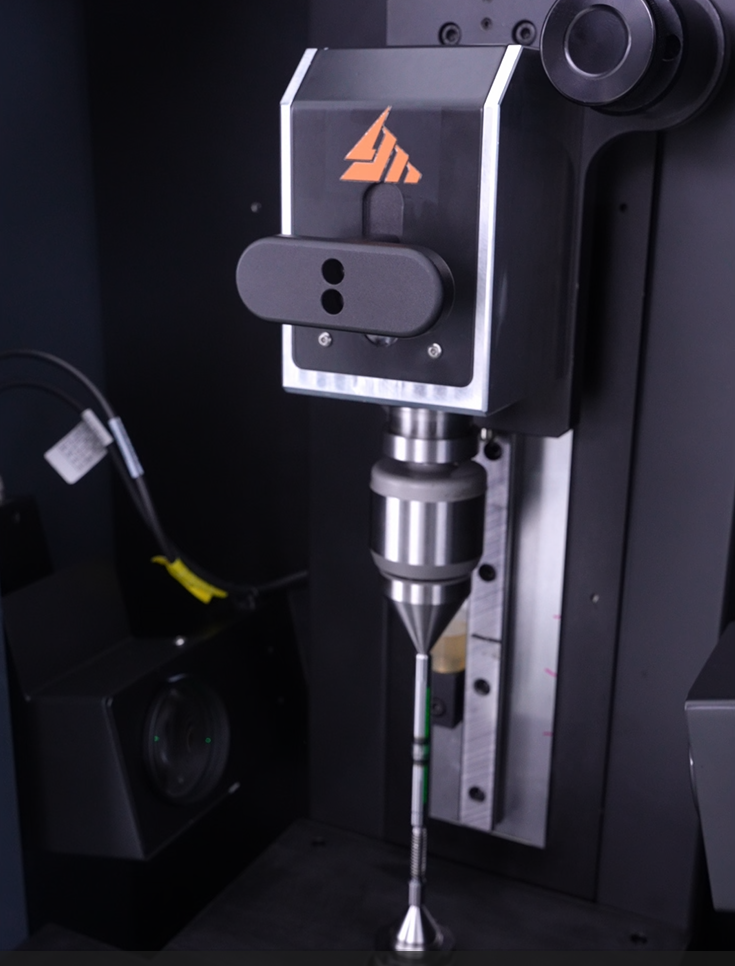
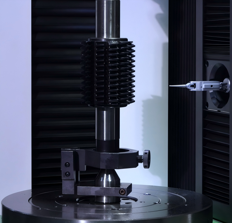
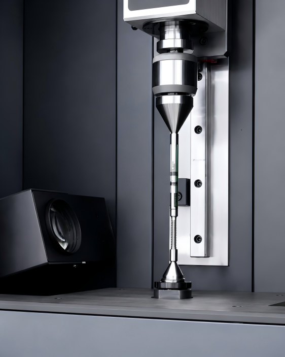
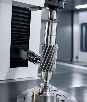
Equipped with a four-axis coordinate measuring system, the ECON 30 achieves precise generative measurement of the worm’s spatial helical tooth surface through the coordinated movement of the X and Z linear axes with the workpiece rotation axis. The system is configured with a high-precision inductive probe from TESA (Switzerland), supporting probe tips as small as 0.2 mm, enabling stable data acquisition for complex worm structures such as small module and narrow tooth slots.
Based on the design parameters and theoretical tooth profile data of the worm being tested, the ECON 30 performs high-precision sampling of the spatial helical tooth profile in a single setup. By comparing the actual measurement data with the theoretical tooth profile, it enables:
· Tooth Profile Error Detection
· Helix error detection
· Lead error detection
· Radial runout detection
· Comprehensive tooth surface error evaluation
All measurement data is generated based on a unified coordinate system, enabling correlated data analysis across different inspection items. This approach prevents reference shifts caused by multiple devices and repeated setups, providing reliable data support for root cause analysis, machining process optimization, and improved transmission performance.
Application value
With the ECON 30 worm gear measurement solution, manufacturers can move from single-parameter inspection to comprehensive tooth surface quality control, improving production consistency, transmission reliability, and problem-solving efficiency.
The solution is widely applied in:
Precision gear reducers and transmission components
For incoming, in-process, and final inspection of worm gear reducers.
CNC rotary tables, swivel tables, and machine tool transmission systems
For quality control of high-precision indexing and feed mechanisms.
Automotive steering systems and automation equipment
For reliable inspection of worm gear pairs in mass production applications.
FAQ
Q: What is the difference between worm gear measurement and involute cylindrical gear measurement?
A: Unlike cylindrical gears with standard involute tooth surfaces, worm gears feature complex spatial helical tooth surfaces with continuously varying lead. Accurate measurement requires coordinated linear and rotary axis movement to capture and analyze the 3D tooth surface.
Q: How do tooth profile errors and lead errors affect worm gear performance?
A: Tooth profile errors influence contact conditions between the worm and worm wheel, while lead errors affect meshing consistency and transmission smoothness. Both parameters need to be analyzed within the same coordinate system for accurate fault diagnosis.
Q: Can ECON 30 measurement data support manufacturing process optimization?
A: Yes. Measurement results can be archived by workpiece information, exported as inspection reports, and fed back into machining processes to support quality traceability and closed-loop manufacturing control.